Mazda 2 Maf Sensor Wiring Diagram
Mazda 2 fuse box. Remove the screws that hold the mass airflow sensor in place.
Dtc P0102 00 Pcm Skyactiv G 2 0 2016 Nd Shop Manual
Control Module Inspection 1.

Mazda 2 maf sensor wiring diagram. It is installed between the air filter and the intake manifold of the engine. The mass air flow sensor measures the amount of air entering the engine or the air flow. Snap acceleration Fig6 DIGITAL MAF WAVEFORMS Gasoline non-turbo - digital MAF sensor.
With the multimeter lead connected to this wire your Mazda MAF sensor should be sending a voltage signal between 15 and 18 volts. Set the multimeter to Volts DC mode and probe the PNKBLK wire of the MAF sensor connector with the red multimeter test lead. Headlights Page L-1 2.
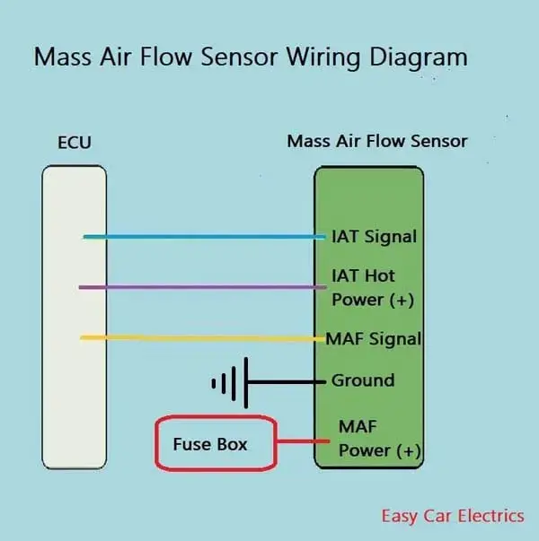
Theres 5 wires coming out of the back of the MAF sensor. Backup Horn Page L-4 Accessories Systems 1. The needle that drops down and is in the hoop of the MAF is the IAT intake air temp part of the sensor.
There is a small hole above that and thats where the actual MAF sensor is you have to spray MAF cleaner up in there. Component Location Chart-2000 MPV. As this Mazda 2 Maf Sensor Wiring Diagram it ends occurring mammal one of the favored book Mazda 2 Maf Sensor Wiring Diagram collections that we have.
They are presented loosely in order from most to least likely. Set the multimeter to Volts DC mode and probe the REDGRN wire of the MAF sensor connector with the red multimeter test lead. Service engine soon light.
MAF Sensor Dirty Over the course of its life the MAF sensor will often get so covered in grime that itll no longer get an accurate readingThey can be cleaned but its easy to mess one up by handling it wrong and you dont want to use a wire brush. Car Hacks and Mods For Dummies David Vespremi 2011-05-09 So you want to. Alright these are the test steps.
The red with green stripe REDGRN wire is the one that connects to MAF. Use two jumper wires to connect terminals 1 and 3 directly to the positive battery terminal. Measure the voltage at each TCM short cord connector wiring harness-side terminal and refer to the terminal voltage table.
In 1920 the Japanese company Mazda was founded which in the first years of its existence was engaged in the creation of machine tools. Unplug the wire harness. Alright these are the test steps.
Remove the air cleaner component. The sensor is located near the engine air filter housing. A lean condition is when there is too.
The vehicle computer may be faulty very rare Read full answer. Install the new MAF on your Mazda. Measure resistance between terminal 2 and terminals 1 3 4 and 5.
Fuse rating A Protected component. Plug the electrical connector until it locks in place. So does anyone know which wire belongs to what on our MAF.
All wiring diagrams for mazda 2 sport 2012 cars car pdf manual diagram fault codes dtc 2013 model 2017 2018 led headlight retrofit 3 hatchback 2004 to 2022 forum and mazdasd forums hi beam digram 6 which wire is high positive negative toyota hilux electrical mazda2 owner s simple bypass foglights works w o headlights or highbeams kia Read More. Check Engine Light appearing on the dashboard. The MAF sensor may be damaged.
If the voltage is not as specified in the Terminal Voltage Table Reference inspect the parts under Inspection item s. Power Mirrors Page A-2 3. History of Mazda Cars.
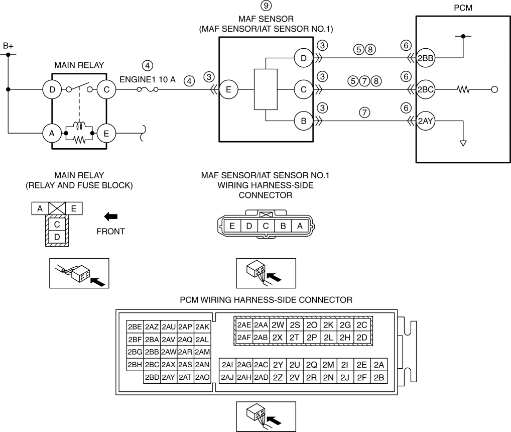
Fuel temperature sensor 179730-0020 RF1L 18 840 Mass air flow meter 197400-2010 ZL01 13 215 Coolant temperature sensor 179700-0220 B593 18 840A Engine compartment temperature sensor 170400-6020 BP4W 18 845 Exhaust temperature sensor 1 265600-1050 RF7N 18 7G0 MAZDA 6 265600-1090 RF7K 18 7G0A MAZDA 5 Exhaust temperature sensor 2. I know that the IAT Intake air temperature sensor is integrated into to MAF sensor but which wires belong to the IAT. May 25 2011 2006 Mazda 6.
Reconnect the MAF sensor and make sure to reference our wiring diagram above in reverse as the diagram is displayed from the face of the connector. The exhaust color is usually darker when running rich. If resistance is greater than 5 ohms go to step 2.
Here are the most common symptoms of a bad or failing MAF sensor. Otherwise the MAF should be fine. A bad mass air flow sensor will usually trigger a check engine light.
The Mass Air Flow sensor MAF is one of the key components of an electronic fuel injection system in your car. Understanding Diagrams Page U-1 Lighting Systems 1. Mazda Fault Codes DTC.
Bosch HFM5 Mercedes C200CDI W204 2007 Condition. Idle Issues Your 2 may run rich or lean when idling or it may also idle erratically. Some MAZDA Car Manuals PDF.
The MAF may be disconnected or a wiring connection may be bad. I need a diagram of the exhaust system on a Mazda 626. This is why you remain in the best website to see the unbelievable books to have.
Mitsubishi Eclipse 18L 1992 Condition. Discussion Starter 1 Sep 24 2008. If this reading shows good you can now either manually.
MX5 Miata RX7 CX7 MPV Mazda EWD s. Tight the screws so that they are snug. Here are the most common causes of P0102 in the Mazda 2.
This is because the ECU will detect an out of range value coming from the MAF sensor and the check engine light is its way of letting you know that something is wrong. If resistance is 5 ohms or less between terminal 2 and any other terminal replace the relay. In modern cars an intake air temperature or IAT.
Stop Lights Page L-3 4. MAZDA Table of Contents Wiring Diagrams 1. A rich condition is when there is not enough air relative to the fuel in the airfuel mixture.
Joined Aug 30 2008. Toyota Auris Corolla 20 D4D 2008 Condition. Faulty PCM less likely but not impossible A code P0103 may mean that one or more of the following has happened.
Door Locks Page A-3 4. Next unplug the electrical connector from the Mazda mass airflow sensor. The pink with black stripe BLKPNK wire is the one that connects to MAF sensor pin D in the illustration above.
Power Windows Page A-1 2. Snap acceleration Fig5 Diesel turbo - analog MAF sensor. Since P0101 has to do with the Mass Airflow Sensor which is a huge part of a computer controlled engines combustion process metering.
1 PCM 2 Mass air flow MAFintake air temperature IAT sensor 3 Throttle position TP sensor 4 Fuel tank pressure sensor 5 Engine coolant temperature ECT sensor 6 Crankshaft position CKP sensor 7 Camshaft position CMP sensor 8 Knock sensor 9. Only show this user. Hopefully you didnt spray carb cleaner.
Fuse block Engine compartment. Turnsignals Hazard Page L-2 3.
Testing
3 4 5 Wire Mass Air Flow Sensor Wiring Diagram Easy Car Electrics


